When college students study electronic courses like Electronic Circuits and Signal Processing, they often only grasp the theoretical aspects of signal characteristics. However, they may not have the opportunity to truly observe or test real signals. The amplitude-frequency characteristic and phase-frequency characteristic are fundamental properties of a signal. To bridge this gap between theory and practice, a frequency characteristic tester based on a single-chip microcontroller (MCU) and FPGA has been designed. This system allows students to visually analyze and measure the frequency characteristics of signals in a hands-on manner.
DesignThe system employs a sweep test method. Let the frequency response be H(jω). When the system is linear with real coefficients, the steady-state output of a linear time-invariant system under the excitation of a sinusoidal signal x(n) = A cos(ω₀n + ψ) is y(n). Using trigonometric identities, the input x(n) can be expressed as the sum of two complex exponential functions:
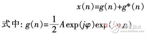
If the input is e^(jω₀n), the steady-state output of the linear time-invariant system is H(e^(jω₀n))e^(jω₀n). Based on the linearity of the system, the response v(n) to the input g(n) is:
Similarly, the output of the input g*(n) is v*(n), which is the complex conjugate of v(n). Therefore, the output y(n) can be written as:
From the above, it's clear that when the system is excited by a sinusoidal signal, the output reaches a steady state, which is a sine wave at the same frequency as the input. The ratio of the output amplitude to the input amplitude gives the amplitude-frequency response, while the phase difference between the two signals represents the phase-frequency characteristic. Thus, the frequency characteristics are measured using a frequency sweep method.
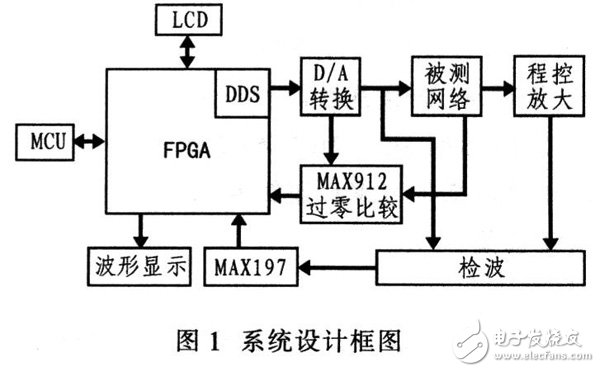
This system uses a single-chip microcontroller and FPGA as the core. A sine wave generated by Direct Digital Synthesis (DDS) is used as the frequency sweep signal. It is input into the network under test, and a peak detection circuit measures both the input and output signals at each frequency point. From their proportional relationship, the amplitude-frequency characteristics of the network are obtained. At the same time, the FPGA counts the number of pulses representing the phase difference between the input and output signals, which is then sent to the microcontroller to calculate the corresponding phase angle. These amplitude and phase values are stored in the FPGA’s RAM and displayed on an oscilloscope along with a sawtooth wave. An LCD screen also displays the start frequency, end frequency, and step size for scanning. For fixed-point measurements, the LCD shows the amplitude and phase of a specific frequency point. The system block diagram is shown in Figure 1.
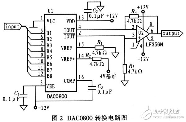
The DDS signal is generated inside the FPGA and converted into a sine wave using a D/A converter. The DAC0800 is used for this purpose. It features an 8-bit resolution, a 100 ns output current settling time, and operates within a ±4.5 to ±18 V voltage range. The sine wave produced by the DAC0800 has 256 samples, which meets the system’s accuracy requirements. The maximum output frequency is 200 kHz, and the 100 ns settling time also satisfies the system’s performance needs. Since the DAC0800 provides only a current output, an operational amplifier is added for I-V conversion. The conversion circuit is shown in Figure 2. Additionally, a low-pass filter is used to smooth the signal and reduce harmonic distortion.
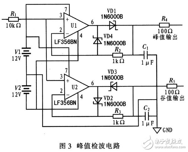
The peak detection circuit works by charging a capacitor during the positive half-cycle of the input voltage. The capacitor is chosen to discharge more slowly than it charges, ensuring that the voltage across it remains at its peak value. This peak voltage is then output through an emitter follower made from an operational amplifier, providing high-impedance isolation. The LF356 operational amplifier is used due to its low input offset voltage, low input offset current, and high input impedance, which helps isolate different stages of the circuit. The peak detection circuit is illustrated in Figure 3.
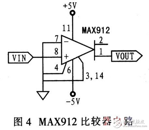
The input and output signals are amplified by an op-amp to generate a square wave that changes in sync with both signals. This square wave is used by the FPGA to count the phase difference. The zero-crossing comparator ensures no phase delay, accurately reflecting the phase difference between the input and output signals. The MAX912 is a high-speed, low-power, dual-channel voltage comparator from Maxim. It offers fast propagation (10 ns) and low power consumption (6 mA per comparator), with independent latch enable functions for each channel. Since the FPGA measures phase based on falling edge detection, a high-speed zero-crossing comparator composed of MAX912 is used. Its circuit is shown in Figure 4.
Unveiling UV Curving Glass: A Leap in Screen Safety
The emergence of UV Curving Glass marks a transformative moment in screen protection, particularly for devices with elegantly curved displays.
Advantages of UV Curving Glass for Device Protection
Devices boasting curved displays can now enjoy a tailored protective solution:
Custom Contouring: UV Curving Glass molds to the specific curves of the screen, providing complete coverage that enhances protection.Clarity Maintained: Manufactured from transparent materials, UV Curving Glass allows your device's display to shine through with crystal clear visibility.Resilient Yet Flexible: Combining the toughness of Tempered Glass Screen Protectors with added flexibility, this protector stands up against scratches and minor impacts without obscuring your device's sleek look.Bespoke Screen Shields with Film Cutting Machines
The tailor-made nature of these protectors is made possible through the use of Film Cutting Machines:
Precision Fit: Film Cutting Machines provide exact cuts of UV Curving Glass for a protector that aligns impeccably with your device's unique screen shape.Customization on the Spot: Say goodbye to the limitations of standard screen protectors. With these machines, protectors are custom-sized for any device, ensuring no screen goes unprotected.Completing the Process with UV Curing
The effectiveness of the UV Curving Glass is realized through the UV Curing Protector Screen:
Effortless and Secure Bond: The UV curing step uses light to solidify the adhesive, delivering a snug, bubble-free adherence to the screen.Speedy and Clean: This innovative method completes the curing process swiftly, significantly speeding up the time to final application when compared to traditional adhesive methods.
Why Opt for UV Curving Glass.Choosing UV Curving Glass Screen Protectors presents multiple benefits for the maintenance and aesthetics of your device:
All-Around Defense: The precise fit and strong construction of the protector mean comprehensive protection from daily wear.
Subtle Protection: UV Curving Glass fits so harmoniously with your device that it's virtually indistinguishable, maintaining each device's design elegance.
Pristine Display: The quality of the UV Curving Glass supports a clear and unaltered view of your screen, ensuring a superior visual experience.Designed to Your Device: With the help of a Film Cutting Machine, every Screen Protector is cut to the exact specifications required for your device.
Dive into Advanced Screen Protection with UV Curving Glass
UV Curving Glass is the pinnacle choice for maintaining the integrity of your device's screen. It offers a perfect union of style and security, presenting an unmatched level of fit and protection. Explore the benefits of UV Curving Glass, empowered by the precise capabilities of the Film Cutting Machine and the adhesive activation of the UV Curing Protector Screen, for the ultimate in modern screen protection.Uv Curving Glass,Tempered Glass Screen Protector,Film Cutting Machine,Uv Curing Protector Screen
Shenzhen TUOLI Electronic Technology Co., Ltd. , https://www.tlhydrogelprotector.com