Introduction
Precision instrumentation systems that measure physical properties using photodiodes or other current output sensors often include transimpedance amplifiers (TIAs) and programmable gain stages to maximize dynamic range. This article illustrates the advantages and challenges of achieving a single-stage programmable gain TIA to minimize noise and maintain high bandwidth and high accuracy through practical examples.
Transimpedance amplifiers are the basic building blocks of all light measurement systems. Many chemical analysis instruments, such as ultraviolet-visible (UV-VIS) or Fourier transform infrared (FT-IR) spectrometers, rely on photodiodes to accurately identify chemical components. These systems must be able to measure a wide range of light intensities. For example, a UV-VIS spectrometer can measure opaque samples (such as used motor oil) or transparent materials (such as ethanol). In addition, some substances have a strong absorption band at certain wavelengths and almost transparent at other wavelengths. Instrument design engineers often add multiple programmable gains to the signal path to increase dynamic range.
Photodiode and photodiode amplifier
Before discussing the photodiode amplifier, quickly review the photodiode. When light strikes its PN junction, the photodiode produces a voltage or current. Figure 1 shows the equivalent circuit. This model represents a typical device used in a spectrometer, including a light-dependent current source in parallel with a large shunt resistor and a shunt capacitor with a capacitance range of 50 pF or less (for small devices) to over 5000 pF ( For very large devices).
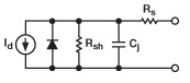
Figure 1. Photodiode model
Figure 2 shows the transfer function of a typical photodiode. The curve looks very similar to a normal diode, but as the photodiode touches the light, the entire curve moves up and down. Figure 2b is a close-up of the transfer function near the origin where no light is present. As long as the bias voltage is non-zero, the output of the photodiode is not zero. This dark current is usually specified with a 10 mV reverse bias. Although operating the photodiode (lightguide mode) with a large reverse bias can make the response faster, operating the photodiode with zero bias (photovoltaic mode) eliminates dark current. In practice, even in photovoltaic mode, the dark current will not completely disappear, because the amplifier's input offset voltage will produce small errors on the photodiode pins.
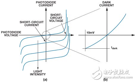
Figure 2. Typical photodiode transfer function
When operating a photodiode in photovoltaic mode, a transimpedance amplifier (TIA) can bias the bias voltage to approximately 0 V while converting the photodiode current to voltage. Figure 3 shows the most basic form of TIA.
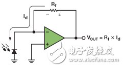
Figure 3. Transimpedance amplifier
DC error source
For an ideal op amp, its inverting input is in virtual ground and all current from the photodiode flows through the feedback resistor Rf. One end of Rf is in virtual ground, so the output voltage is equal to Rf × Id. In order for this approximation to hold, the op amp's input bias current and input offset voltage must be small. In addition, a small input offset voltage can reduce the dark current of the photodiode. A good choice for the amplifier is the AD8615, which has a maximum leakage current of 1 pA at room temperature and a maximum offset voltage of 100 μV. In this example, we choose Rf = 1 MΩ to provide the desired output level under maximum light input conditions.
However, designing a photodiode amplifier is not as simple as selecting an op amp for the circuit shown in Figure 3. If you simply connect Rf = 1 MΩ across the feedback path of the op amp, the shunt capacitor of the photodiode will cause the op amp to oscillate. To illustrate this, Table 1 shows the Cs and Rsh of a typical large area photodiode. Table 2 lists the main features of the AD8615. Its low input bias current, low offset voltage, low noise, and low capacitance make it ideal for precision photodiode amplifier applications.
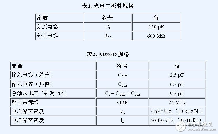
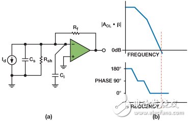
Figure 4. Photodiode amplifier model (a) and open loop response (b)
Stainless Steel Lost Wax Casting
Lost Wax Casting,Steel Lost Wax Casting,Stainless Steel Lost Wax Casting,Lost Wax Stainless Steel Sand Casting
Dongguan Formal Precision Metal Parts Co,. Ltd , https://www.formalmetal.com