Communication equipment usually adopts a multi-line card and backplane architecture. There are multiple card slots on the backplane, and the line cards are plugged into these slots. The line card carries the service, and the backplane provides a system data bus and a power bus. The line card interconnects and communicates with the main control board through the bus on the backplane. Once the entire device is powered on, it must continue to work and cannot be powered off. Line cards may need to be repaired, upgraded, configured, or expanded throughout the life of the equipment. This requires the card to be pulled out/inserted while the backplane is powered, and the system cannot be powered down during the entire process. In order to reliably implement this hot plug process, the impact on the backplane power bus is controlled, usually using a hot swap circuit. In order to further improve the reliability of the system, the communication device also adopts a power backup architecture. When the main power supply is damaged, the backup power supply will cut in time to ensure the normal operation of the equipment.
The OR logic control circuit is used to implement this power switching function. Hot-swappable circuits and OR logic control circuits provide a highly reliable solution for multi-line card and backplane devices such as communication devices.
The basic principle of hot plugging
The power inlet side of the line card usually has a capacitance of several hundred microfarads to several thousand microfarads for power supply filtering and energy storage. When the entire system is working, the line card inserted on the backplane has full capacitance on the inlet side. These uncharged capacitors are charged when another line card is inserted into the running backplane. Because the contact between the line card and the backplane metal member occurs in a very short time, the line capacitor has a high capacitance of the inlet capacitor, and the charging current can be large, as shown in FIG.
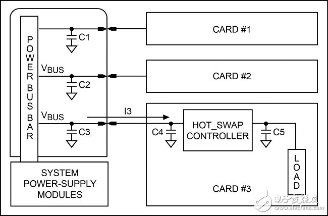
Figure 1. Current flow when inserting a line card
In Figure 1, when the line card is plugged in, C4 is quickly charged, a portion of the charging current comes from C1, C2, and some charging current is supplied by the power module. Depending on the system design, the charging current can reach several hundred amps in a short period of time.
This current surge can cause a drop in the backplane bus voltage, which in turn causes a system reset. This uncontrolled current surge process can also cause damage to the system, such as damage to the filter capacitor, PCB traces, and backplane connectors.
The best way to deal with this phenomenon is to use a hot-swap controller to control the peak value of the inrush current during plugging and unplugging.
Backup power
Highly reliable communication systems often use a backup power architecture to increase system reliability. When the main power supply works abnormally or fails, the backup power supply will cut in time to maintain the system operation. In this architecture, a common method is to use a pair of diodes to construct the "or" logic of the power supply, connected between the main/standby power supply and the load. The disadvantage of this circuit is that the diode has a high forward voltage and a high loss on the diode. The OR logic controller is used to mimic the electrical characteristics of the diode while reducing the losses in the overall system.
Use dual channel hot swap, OR logic controller
The low dropout OR logic switch controller independently controls the back-to-back nMOSFET of each channel for hot swap and OR logic control. The controller has four MOSFET drivers (GATE1_ and GATE2_) built in. GATE1_ controls the external n-channel power MOSFET to implement OR logic to prevent current flow between the main/standby power supply or current between IN and IN. GATE2_ control external The n-channel power MOSFET implements hot swapping. Precision resistors on the path for current sampling.
Magnetic Transducer,Smd Magnetic Transducer,Buzzer Magnetic Transducer,Magnetic Transducer Buzzer
NINGBO SANCO ELECTRONICS CO., LTD. , https://www.sancobuzzer.com