introduction
Currently, there are many applications (such as immersive virtual reality and technology visualization computing) that benefit from high-definition displays. Unfortunately, the existing projection technology is still limited to XGA (1024 & TImes; 768) or SXGA (1280&TImes; 1024) pixel resolution, and at the time of writing, the latter is quite expensive. Fortunately, we can stack multiple low-end commercial projectors, each driven by a different computer or driven by different graphics channels in the same computer.
The first problem encountered with commercial projectors is that these projectors are different from those of the more expensive models, and they do not have built-in support for spliced ​​displays. In addition, the structure of their optical system makes it impossible to reliably adjust multiple projectors in a pixel perfect (or close) manner. Since the splicing display is not perfect for pixels, the end result can only be that there is either a gap between the images or a seam with twice the brightness; both cases are annoying, especially for those This is especially true for content shot in panning or for subjects that are crossing the gap. The solution is to have a considerable overlap between the two images and then adjust the pixels in the overlap so that the overlap is as invisible as possible. This approach works because after doing so, any tiny projectors are improperly calibrated or the lens aberrations are only slightly blurred, without sharp seams or gaps.
overlapping
The first step in the process is to overlap the two images. This article will use an internal panorama of an iconic building in Sydney. The pixels of the overlap region will be fused in the entire overlap region, that is, the two images will fade to black. This general approach is quite applicable to any number of images, as well as to images that may not be arranged in a rectangular manner. The projector used here is XGA (1024 & TImes; 768) with 256 pixels in the overlap region. The overlap is not necessarily exactly the power of 2, but since the image is blended with texture and OpenGL, the power of 2 is the most efficient. The degree of overlap depends on the amount of gamma correction required (see below) and the dynamic range of the blending function. In this case, the same good result as 256 pixel overlap cannot be obtained with 128 pixels. Therefore, the final image width is 2 & TImes; 1024-256 = 1792 pixels and the height is 768 pixels.

The figure below illustrates the two projected images. As expected, the overlap area is brighter than the normal image because it is shared by the two projectors. The application used to display this panorama is a natively developed look-ahead program for viewing stereo panoramas, written for OpenGL-based graphics. It's very easy to generate these two overlapping images with OpenGL, because you only need to make the corresponding changes in the view cone. Please note that the images shown here are digital photos of these images taken in the darkroom, and it is difficult to display them because the colors of these photos look a little faded.
Fusion
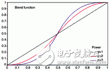
Blending is the multiplication of each pixel in an image in the overlap region by a value such that when it is superimposed on its corresponding pixel in another image, the desired pixel value is obtained. This is easily accomplished with a function f(x) with a range between 0 and 1: for example, the pixel in the right image is multiplied by f(x), and the corresponding pixel in the left image is multiplied by 1- f(x). The functions used in this article are given below. There are many possible options, but we chose this function because it allows us to experiment with exact functional forms from linear to highly curved.


The graphical representation of this function is as follows. Note that the coordinates in the graph have been normalized to 0 (indicating the beginning of the edge blending region) and 1 (indicating the end of the edge blending region). Taking the image on the right side as an example, the pixels in the first column are multiplied by 0 (no effect), and the pixels on the right edge (column 255) of the blending region are multiplied by 1. The blending function of the left image is 1 - the curve is as follows. At the midpoint of the blending zone, the curve passes through 0.5, which indicates that the pixels in each image contribute equally to the final pixel value. The exact curvature depends on the parameter "p". When p=1, the mixing is linear; as the p value increases, the jump around 0.5 becomes steeper and steeper, and p=1 is likely to cause the edge of the mixing zone. A visible step appears. All examples in this document use p=2.

Edge blending is achieved by placing a polygon, and the edge blending function described above is represented as a grayscale one-dimensional construct. This constructed polygon is properly blended (in OpenGL) to make it possible to trim pixels in the image buffer. The advantage of this approach is that it can be adapted to any OpenGL application at will because it is a post-processing work done after the normal geometry drawing is completed. The figure below illustrates the construction of the masking area over the entire mixing zone.
The image below is a screen dump of the image seen on a computer (with dual display), ie a panoramic image multiplied by the masking function described above. The resulting projected image is as follows, but why is there a gray bar?

Gamma correction
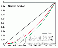
The above mixing function is not enough. The reason why there is a gray bar in the previous image is because the method we have introduced so far only increases the pixel value, but what really needs to be done is to increase the brightness level of the image. The main function used to control how pixels are mapped into brightness is the so-called gamma function of the display, which typically ranges from 1.8 to 2.2. Gamma is the correlation between pixel values ​​and output brightness; if G represents a gamma function, the output brightness is the power of the pixel of the pixel value (normalized to be between 0 and 1).

Fortunately, this can be easily corrected using the inverse power of gamma. Therefore, the complete transformation of the image pixels is the functions f(x)1/G and f(1-x)1/G.

Below is a gamma-corrected edge blend image. Note that in general, gamma corrections are required for each of the r, g, and b values ​​because they use different projectors.
further improvement
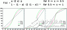
Below is a modified edge blending function that provides some brightness control at the center of the blending zone. The value of "a" ranges from 0 to 1, and if it is greater than 0.5, the center of the mixing zone becomes brighter; if it is less than 0.5, the center of the mixing zone becomes dark.

Projector black level

To what extent the mixing zone becomes invisible, the main constraint is the extent to which the projector generates black levels. CRT projectors typically have the largest black level, but such projectors are unpopular for other reasons (large size, need for calibration, low illumination, etc.); LCD projectors typically have poor black levels; DLP The projector is better (the DLP projectors are used in these tests). The main indicator of black level published by the manufacturer is contrast. At the time of writing, many projectors have a nominal contrast ratio of about 1500:1 to 2000:1; some projectors have a nominal contrast ratio of 3000:1 or even 3500:1. In general, there is some sort of exchange between projector brightness and contrast, and most users want a projector with a higher brightness, but at the expense of a poor black level.
4 layer PCB Board
Storm Circuit Technology Ltd , https://www.stormpcb.com