Author: Arnold Jansen, Alcatel-Lucent
The core router's cooling and power management is a hot topic for many years. This trend will persist for a long period of time as broadband traffic continues to grow exponentially.
However, reducing environmental impacts and operating costs have always been the top priority, allowing network operators to think about the problem of “what we do not exceed the actual available space, power, and cooling resources in the NOC. Network capacity requirements are facing challenges.
The growth of traffic creates a vicious circle in the Network Operation Center (NOC): higher energy consumption is required to support more equipment, more equipment generates more heat, and stronger cooling is needed to keep the equipment working at its best. Within the operating temperature range, more cooling will consume more energy.
Facing the ever-increasing costs, the expansion based on existing power and space is the top priority for adapting to the growing demand for router capacity.
Core router capacity and energy efficiency
The capabilities of the core routers have always kept pace with the gradual increase in Internet traffic. However, due to the higher requirements for scalability and density, energy consumption, cooling efficiency, and space efficiency have become key design constraints. Unfortunately, there is a lag in energy efficiency improvements: The power limit for a single rack is currently about 20 kilowatts. At this rate, single-rack switching capacity is facing significant problems in the future. (figure 1)
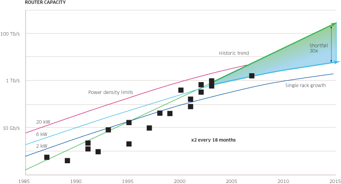
Figure 1 Single-rack router capacity growth forecast
With the increase of power efficiency, cooling efficiency, and port density of each rack, service providers can expand their core network capacity with less space, thereby greatly reducing operating costs.
The good news is that these efficiencies can be improved by optimizing the design. Like the Alcatel-Lucent 7950 XRS high-performance core router is leading the direction of development with comprehensive design, management and energy-saving solutions.
Improve power efficiency through design
Today, the Alcatel-Lucent 7950 XRS has achieved a power efficiency of 1 watt/Gb/s (16 Tb/s normal power consumption of 16 kW). The results achieved advanced performance and efficiency through advanced design.
â— Faster, more efficient and fewer devices â— Optimized frequency and voltage, maximum speed with minimum power consumption â— FP3 network processor intelligent power management â— Improved DC-DC power converter technology â— Line card only when in use Power supply â— Optimized load sharing and power input module filtering
Start with the chip level
Start smart power management and cooling from the chip.
The faster chip has a series of advantages. For example, in the 7950 XRS, 400Gb/s forwarding capability provides the perfect architecture for 10, 40, and 100G port densities for non-blocking switching. Its high performance enables it to implement more efficient memory pool sharing for routing and forwarding information relative to other chips. And fewer chips will reduce power consumption and potential points of failure.
In an optimized design, the chipset that powers the core router embeds built-in logic that will turn off unused features and save power. Power input modules, as well as power-consuming system components such as line cards, are also intelligent. This will enable active monitoring, managing energy and cooling, and maintaining safe and energy-efficient operating conditions.
Power bus structure
Some routers are designed to divide a system into different areas powered by dedicated power supplies. The disadvantage is that each area needs to be individually protected or bear the risk of failure of the entire router due to the failure of a critical area.
In contrast, the power bus architecture used by the core router allows power resources to be shared in the most economical way and improves overall system reliability.
A single internal common bus design allows existing power supplies (including the N+M model) to be shared among all system components, and an intelligent power input module can track the power ratings of individual system components. They communicate with each other, track the total available power, and shut off the supply of non-critical components when the system fails to supply power.
The growth of the core router system should keep up with the demand, and the bus architecture makes it possible to add power supply and components only through the new power input module. If one power module fails, it can be safely replaced without touching or modifying any power cable. For rare cases of multiple power failures, critical systems such as control processor modules, cooling fans, and switch fabric modules will be protected.
Heat dissipation design for optimal heat dissipation
Thermal design is an important aspect of a carrier-grade routing platform, but it is often neglected. This is an oversight that network operators cannot afford
Heat dissipation determines the maximum system capacity and port density. The system design must start at the lowest level and define where to deploy the continuous and reliable cooling functions that cover all components.
What are the necessary elements of thermal design?
◠Frame height and slot width for special space design for air movement ◠Air intake area optimized for maximum air flow ◠Air guides that distribute air evenly around the right and left ◠Impedance plates that ensure equal air flow per slot ◠Make sure State-of-the-art fan technology for quiet and efficient cooling. ◠“draft†air flow design that pulls air through all chassis components. ◠Cool air is drawn from the cooling channel side of the chassis.
Cold/hot channel separation
The clear layout of the "cold" and "hot" channels in the NOC provides an optimal thermal design opportunity. The cooling channels are used to provide cold air at the cooling inlet of the system, while the cooling channels allow heat to be dissipated without affecting the cold air channels of the peripheral equipment. A well-designed routing device will maintain a clear separation of the hot and cold separation channels; only the air is taken from the cooling channels and the hot air is discharged from the cooling channels.

Figure 2 Cold/Hot Channel Separation of the 7950 XRS
Cooling area
The core router can be divided into one or more cooling zones, but multiple cooling zones will lead to unnecessary complexity. More fans are needed to cool each area and require more air filters. If designed properly, even a full rack core router can have only one cooling zone.
"Extract" airflow for effective cooling
"Pumping" airflow design is essential for efficient and continuous cooling of core routers. The system's airflow creates a vacuum throughout the system, ensuring that all components are properly dissipated and no hot spots appear. One approach is to use a large number of separate airflows from side to side, from front to back. This allows a separate and balanced flow of air through all components without turbulence. Directing the air to evenly distribute cold air over all components optimizes and enhances cooling efficiency.
Avoid "propulsion" airflow design. In high-performance communication equipment, it is rarely found that an extra large area is required between the "propulsion" fan and the line card. Additional areas allow air flow to converge from multiple fans to a single air stream. Without preconvergence, the turbulence generated by the fan will enter the card cage area and cause hot spots, air circulation in the device and harmful air flow.
Efficient fan design and active control
The best practical design provides a 1+1 redundant dual fan tray and a dedicated programmable controller for each fan for small particle speed increases. By actively controlling the fan speed, different thermal characteristics of the system components can be accommodated and the environmental conditions can be changed when the system configuration changes. When the operating environment allows the fan to be slower, power consumption and noise can be reduced.
By defining overheating conditions, activating backups to avoid air leaks that compromise vacuum, rules such as fan operation, speed, and power consumption can be monitored through an intelligent management system.
In front-to-top cooling NOCs, efficiency can be further increased by vertical exhaust from the top rack exhaust. The headroom expands the available air space and reduces windage.
Intelligent management of power and cooling
Intelligent power and cooling management is indispensable in the next generation of core routers. It can help network operators:
â— Monitor and ensure that all system components have sufficient power supply â— Avoid wasting energy on the power supply of unused system components or circuits â— Prevent local power cuts, reduce the impact of power system availability on system operation â— Ensure that the system runs safely at the best Temperature â— Reduce noise â— Minimize operating costs
The 3D LED Ball can be for indoor and outdoor. We cooperate with other famous design organizations to make a big improvement on LED 3D control technology, and developed many 3D visual products, like the ball string(40mm 3D Led Ball string, 50mm 3D Led Ball string), and the big Magic Led Ball with different size, and Kinetic Led Ball ( Kinetic Balls) to built ball sphere. The 3D balls control mainly by DMX 512 protocol, and easy to built the led lighting system.
3D LED Ball
3D Led Ball,3D Ball,3D Led Ball,Led Ball
Shenzhen Iseeled Technology Co., Ltd. , https://www.iseeledlight.com