With the continuous development of automotive electronic technology, the number of electronic control units on the vehicle is increasing, and the functions are becoming more and more complex. The interconnection, coordination and sharing of information between multiple processors constitutes a vehicle-mounted computer communication network. The vehicle network uses multiplex transmission technology, and uses multiple buses of different speeds to connect different types of nodes, and uses a gateway server to realize information sharing and network management of the entire vehicle. Among them, CAN (Controller Area Network) bus technology has been widely used in automotive in-vehicle networks. The physical layer protocol and data link layer protocol of the CAN bus have been widely known as international standards, and have been supported by major international chip manufacturers. Various CAN network protocol chips and physical layer chips have become quite popular. Due to the different applications, the protocol of the application layer is a hundred schools of thought. Among them, DeviceNet, CANopen, etc. are mainly used in industrial sites. The protocols applied to trucks and buses mainly include SAE J1939 [1]. However, there is no uniform standard for application layer protocols applied to cars. This is because the application layer agreements of cars of various manufacturers are the result of years of accumulation and are not disclosed as confidentiality agreements. This is also the reason why China's car industry has lagged behind in the application of CAN bus in recent years. This paper mainly studies the basic core of the CAN CAN body network application layer protocol, based on the network management of OSEKÎ VDX, and gives the key design methods.
This article refers to the address: http://
2 Network Management Foundation
2. 1 Introduction to OSEKÎ VDX
The error handling capabilities of the CAN protocol and the EMC resistance of the physical layer ensure the relative reliability of the CAN nodes. But for CAN
For the network, the reliability of a single node does not represent the reliability of the entire network. In order to ensure the reliability of the entire CAN network, network management functions must exist. Network management ensures the coordination of each node and monitors the operating status or error of other nodes on the network. The main reference standard for automotive CAN network management is OSEKÎ VDX.
OSEKÎ VDX is a set of standards for distributed real-time structures developed by a community of European car manufacturers and suppliers in collaboration with the University of Karlsruhe, Germany. It contains four standards: operating system (OS), communication (COM), network management (NM), and OSEK implementation language (OIL). Many electronic control units (ECUs) of OSEKÎ . In different designs, coding and expertise can be reused, and common interface standards can be used to achieve significant savings in industrial production. The operating system that complies with OSKEÎ VDX has been studied in China, but there is no relevant article on network management. This paper mainly studies the indirect management method of body network based on CAN network, and proposes a specific implementation.
2 2. 2 The transmission mode of the CAN bus network frame can be divided into three types of transmission modes: event type, periodic type and hybrid type according to different trigger conditions [3].
2 2. 2. 1 Event transmission mode
A message that is sent in time as the type or data changes. The benefit of this type of message is that it occupies very little bus resources, but there may be situations such as missed hair. This type of message is similar to the interruption of the network, and the frame used for troubleshooting can be event type.
2. 2. 2 periodic transmission mode
The type of message that is sent cyclically over a period of time. The time precision required for this type of message is generally less than 10%. The reliability of the message can be guaranteed as much as possible. If the period is too short, the load of the bus may be too large, which may affect the quality of the network. In the design of the network, the following basic rules can be observed: if the frame ID number is smaller, its priority is higher, then its period can be smaller. The frames used to supervise the state of the network can be periodic.
2. 2. 3 mixed transmission mode
That is, a frame of an event type and a periodic type. The event type message transmits a frame that changes in real time, and the periodic transmission ensures the completeness of the message. For example, if the frame used to monitor the external device does not change, the parameters will be sent periodically. If the parameters in the frame change, the frame will be sent as an event, then re-timed and sent in periodic mode.
The classification of the three transmission modes makes the types of frames in the CAN network clearer, which is conducive to the development of application layer protocols and network management rules.
3 Network management method
3. 1 OSEKÎ VDX NM Study
Because the operating environment of the car is relatively harsh and the safety requirements are very high, the requirements for the communication network are very strict. The main task of OSEKÎ VDX network management is to ensure the security and reliability of the communication network between ECUs [2]. Since the structure and characteristics of each network are different, the implementation of network management is different.
OSEKÎ VDX provides two network management mechanisms for direct monitoring and indirect monitoring. Direct monitoring is directly monitored by the marked communication mechanism. Each node in the network is monitored by other nodes, so each controlled node will issue a specific unified network relationship message. Direct monitoring synchronizes network monitoring information through a logical ring. Each node on this ring has an address that can be detected by a dedicated one-way network independent of the network protocol, and the status of each node on the network can be detected. Direct network management is highly reliable, but requires more time and increases network load and CPU load.
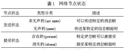
Indirect network management is based on the periodic information frame that supervises the ECU nodes. That is to say, a periodic frame sent by one node is received by one or more nodes, and the receiving node completes indirect network management by supervising this periodic frame. Indirect network management node status type classification description is commonly used in central control networks, there is a powerful gateway to send status non-silent (not mute) can transmit specific message frames as the main ECU of network management, other node ECU is silent by the gateway (mute) Transmits a specific message frame timeout monitoring. Each node ECU must implement a specific periodic acceptance state to present a frame that can be accepted by a particular message frame to be supervised. A network node has two absent states: accept state or send state, as shown in Table 1.
3. 2 CAN body network status management
In order to achieve low power consumption of the body network, the gateway system will coordinate control. In this state, only external wake-up frames, or internal wake-up frames, etc., can be accepted, and the function information frame cannot be received [4].
Figure 1 shows the transition diagram for the four network states. The direction of the arrow is the direction of the ECU state transition, and the initial state of the ECU enters the sleep state. If there is a wake-up command from the gateway, the ECU enters the awake state. If the command of the normal state of the gateway is received in the awake state, the ECU enters the normal state. Other state transitions are similar to [5].
4 Network management design method
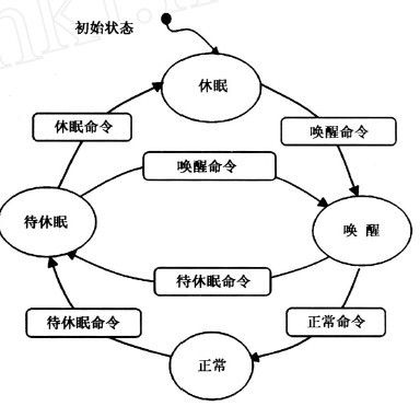
Figure 1 Network state transition
The network node ECU uses the C MUTE and C ABSENT counters to determine if the node has reached MUTE or ABSENT. When the counter reaches 255, the node has failed. When the fault occurs or disappears, the ECU sends the fault frame to the gateway through the event type frame. The fault frame design example is shown in Table 2.
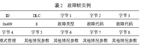
The frame ID is 0x499 and the DLC is 8. The first byte indicates whether the fault occurred or disappeared. The 2nd and 3rd bytes indicate the fault code, and the 4th byte indicates whether the function is degraded after the fault. The 5th to 8th bytes indicate other conditions of the fault. The counting addition and subtraction rules for C MUTE and C ABSENT are done by supervising frames of different periodic types. For C MUTE , if the ECU does not successfully send a frame of data, C MUTE adds up to 255 and the fault is acknowledged. If the ECU successfully sends a frame of data, then C MUTE is decremented until 0 and the fault disappears. Similarly, for C ABSENT, if the ECU does not successfully receive a frame of data, C ABSENT adds up to 255 and the fault is acknowledged. If the ECU successfully receives one frame of data, then C ABSENT is decremented until 0 and the fault disappears. In the actual example, for a frame with a period of 200ms, if the 3 frames of data are not successfully transmitted or received successfully, the increment is 77 and the decrement is 26 . For a frame with a period of 100ms, if the 3 frames of data are not successfully transmitted or received successfully, the increment is 39 and the decrement is 13. Therefore, if such a network management method is used, each ECU must have a frame transmitted in a 100ms or 200ms period. The fault types of C MUTE and C ABSENT can be defined on their own. Figure 2 shows the C-ABSENT counting rules for node K, which represent the technical rules of node K, the relationship between the missing or existing state of node K and the counter, and the extended state of node K.
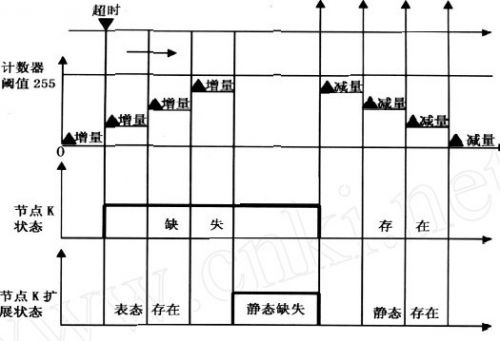
Figure 2 C ABSENT counting rules for node K
Another frame that implements network management is the supervised frame. The supervised frame is a periodic frame, and the ECU sends the supervised frame to the gateway in cycles. The main contents include the physical error of the ECU's CAN bus (if it is low-speed fault-tolerant CAN), whether the ECU unit is ABSENT, whether the ECU unit is MUTE, the ECUOFF number of the ECU unit, and the number of times the ECU unit sends a timeout error [6]. Through these parameters, the gateway will know the current operation of the ECU. If an error condition occurs, the gateway will record these errors in the EEPROM, which will help the maintenance personnel to perform post-diagnosis through the diagnostic tool and can determine the random failure that is difficult to track while driving.
5 Summary
With the continuous improvement of China's technological strength and the adjustment of national policies, Chinese auto companies will no longer only focus on the market, and are gradually focusing on breakthroughs in core technologies. The supporting project of this paper is implemented in this context. The network management method and network state management based on CAN network have been applied in a certain model and run well, which proves the feasibility and reliability of the method.
Semi-harvester for Agriculture:
The semi-feeding harvester can complete the harvesting, delamination, separation of stems, removal of sundries and other processes at one time, and the Rice Harvester machine for obtaining grain directly from the field is mainly suitable for rice harvesting, wheat harvesting, and this reaper machine can adapt to deep mud feet. Under the serious harvest conditions, the grain cleanliness after harvest is very high, and at the same time, the stem integrity after harvest can be guaranteed, so that farmers can complete harvesting and granulation with a single operation, thus saving manpower and material resources and greatly reducing the burden of farmers.

Semi-harvester for Agriculture Technical Parameters:
1. Size: 3650*1800*1820 (mm)
2. Weight: 1480KG
3. Engine Fuel: Diesel
4. Harvest numbers line: 3
5. Harvesting width: 1200 (mm)
6. Cutting height range: 50-150 (mm)
7. Threshing depth control system: Manually
8. Adaptation crop height: 650-1200 (mm)
If you have any questions, please contact us directly. Crawler tractor for agriculture are produced by Hunan Nongfu with high quality and good appearance.
welcome you can visit our factory for inquiry, please send mail directly to us.
Semi-harvester for Agriculture
China Harvester Machine, Rice Harvester, reaper machine, Agriculture equipment
Hunan NongFu Machinery&Electronic.Co., Ltd. , https://www.nfagmachine.com