Foreword
This article refers to the address: http://
Having good taillight performance is essential to the car and an important part of driving safety. The flashing of the taillights of the car is not erratic (electric car controller), it is constantly changing according to the direction in which the car is traveling. The taillight control circuit (automobile control system) is closely related to the change of the taillights of the car. In short, the taillight control circuit of the car controls the changing law of the taillights of the car. Then the working principle of the car taillight control circuit and how it is designed? The author summarizes the relevant knowledge of the car taillight control circuit (automotive electronic control technology) by collecting and sorting data.
How the control circuit of the car taillight works
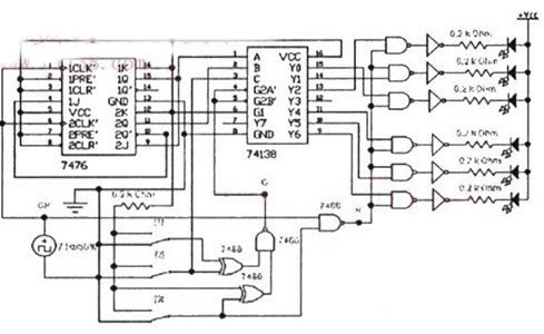
The vehicle taillight control circuit includes a decoding circuit and a display driving circuit. The display driving circuit is composed of 6 light emitting diodes and 6 inverters (7404); the decoding circuit is composed of a 3-8 line decoder 74138 and 6 NAND gates (7400). The three inputs A, B, and C of the 74138 are connected to the output terminals 1Q, 2Q and the steering control switch [2] of the ternary counter, respectively. When [2]=0, the enable signal G=0 (decoder operation), S=1, the state of the counter is 00, 01, 10, the output terminals Y0, Y1, Y2 corresponding to 74138 are “0â€. "Effective, that is, the output terminals of the inverters G1 to G3 are also 0 in order, so the indicator lights up in the order of D3â†D2â†D1. If the above conditions are unchanged, and [2]=1, then the output terminals Y4, Y5, and Y6 corresponding to 74138 are 0 active, that is, the outputs of the inverters G4 to G6 are sequentially 0, so the indicator light is pressed D4→D5. → D6 lights up in sequence. When G=1 (decoder disables decoding), S=1, the output of 74138 is all 1, the output of G1~G6 is also all 1, the indicator light is completely off; when G=1, S=CP, the indication The light flashes with the frequency of the CP. ("1" means high level, "0" means low level), and the current limiting resistor in the circuit has a value of 0.2 kΩ. The car taillight control circuit is shown in the figure.
Car taillight control circuit diagram
This circuit uses several cheap transistors and two relays to make the bus's twitching country signal and cornering signal comprehensively control the taillights; both taillights are on when braking, and only one taillight is on when cornering. The turn signal causes the taillight to illuminate twice per second. C1 and C2 are charged to the peak pressure of the turning signal when cornering. The size of the capacitor is such that the relay can pick up during the gap time of the flash. If the capacitor is chosen too much, the brake signal will not immediately light up the taillights after the cornering signal is removed. This circuit is designed for new cars that need to separate the cornering signal from the braking signal for safety reasons.
Automotive taillight control circuit design
There are 3 indicator lights on the left and right sides of the rear of the car. When turning left, right, brake, and check, the indicator flashes as specified.
The design requirements of the vehicle taillight control circuit are as follows: Assume that there are three indicator lights on the left and right sides of the tail of the car (simulated by LEDs).
(1) When the car is running normally, the indicator light is completely off;
(2) When turning right, the three indicators on the right side are illuminated in the right cycle order;
(3) When turning left, the three indicators on the left side are illuminated in the order of the left cycle;
(4) When the brake is temporarily applied, all the indicators flash simultaneously [2]. Use three switches to control the lighting state of the indicator.
According to the design requirements, draw a block diagram of the car taillight control circuit, as shown.
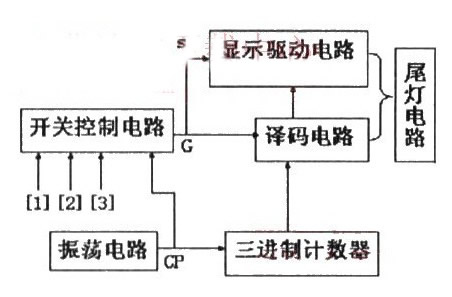
Block diagram of car taillight control circuit
According to the design requirements, the taillight control circuit of the automobile is composed of an oscillating circuit, a ternary counter, a decoding circuit, a display driving circuit and a switch control circuit. Since the three lights are cycled when the car turns left and right, the hexadecimal counter is used to control the decoder circuit to sequentially output a low level, thereby controlling the tail light to illuminate as required.
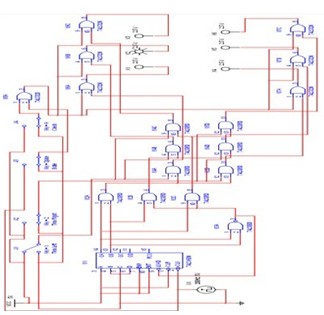
Simulation Design of Automobile Taillight Control Circuit
The modules are connected into a complete simulation circuit, and the clock control signal CP directly uses the pulse signal source in the EWB software platform. as the picture shows:
Block diagram of control circuit simulation of automobile taillights
After the above analysis of the design content and requirements, the circuit can be divided into the following parts:
First, a pulse signal having a frequency of 1 Hz is generated by the 555 timer, and the pulse signal is used to supply an input signal to the D flip-flop and the brake.
Three D flip-flops are used to generate a cyclic signal of 001, 010, 100 for the three-terminal output, which provides the original signal of left turn and right turn.
The original signal of the left turn and the right turn is output to the left and right three taillights through the high and low potential signals provided by the six AND gates and the electric keys. This part of the circuit acts as a signal sorter.
The signal after sorting passes through the OR gate to achieve the choice between braking and checking the signal of the key. The resulting signal can be output to the LED to achieve the desired function.
to sum up
In today's society, automobiles have become an indispensable means of transportation in people's lives. Automotive taillights are an important part of the car's construction, and the taillight control circuit is also very important. This paper mainly introduces the working principle, design scheme and simulation design of the vehicle taillight control circuit.
5730 SMD LED supplier from China
For 5730 SMD LED . They can be all kinds of wavelength's SMD LED, include the visible Light and the unvisible light.
In this catalog, we mainly introduce the 5730 SMD LED of visible light. 5730 SMD LED, size is 2.8*3.5mm. For this SMD LED, we can supply all kinds of visible wavelength and color on it. such as: purple LED, blue LED, cyan LED, lime LED, green LED, Yellow LED, Amber LED, Orange LED, red LED, deep red LED, red grow light LED , white LED, warm white LED, pink LED and so on.
With 5730 SMD LED, we supply: purple 5730 SMD LED, blue 5730 SMD LED, cyan 5730 SMD LED, lime 5730 SMD LED, green 5730 SMD LED, yellow 5730 SMD LED, amber 5730 SMD LED, orange 5730 SMD LED, red 5730 SMD LED, deep red 5730 SMD LED, red grow light 5730 SMD LED , white 5730 SMD LED, warm white 5730 SMD LED, pink 5730 SMD LED and so on.
Normally, the angle of those 5730 SMD LED is 120 degrees. We also can customize that angle as your needed, like 30 degrees, 45 degrees, 60 degrees, 90 degrees ect.
5730 SMD LED
5730 SMD LED, High Brightness 5730 SMD LED, SMD LED 5730, 5730 SMD LED 0.2W
Shenzhen Best LED Opto-electronic Co.,Ltd , https://www.bestsmd.com